2013/10/29

Fiber Jumpers Inspection And Cleaning Methods


Optical patch cords used as jumper cables, also called fiber optic jumpers, are often used between the optical transceiver and fiber terminal box. The main purpose of fiber optic jumpers detection is to ensure the quality of system connection, reduce the failure factors, and identify the fiber point of failure in the event of a failure. There are many detection methods which are mainly divided into artificial simple measurement and precision instruments measurement.
  • Artificial Simple Measurement: This method is generally used to rapidly detect the fiber jumpers' ON/OFF and distinguish fiber jumpers in construction. It uses a simple light source to infiltrate visible light into the fiber optic jumper from one end, and observe which one glows from the other side to achieve the detection. Although this method is simple, it can not quantitatively measure the attenuation and breakpoint of fiber optic jumpers.
  • Precision Instruments Measurement: Using the optical power meter or optical time domain reflectometer (OTDR) to quantitatively measure the fiber jumpers, the attenuation of fiber jumpers andconnectors can be measured, even the breakpoint position of fiber optic jumpers can be measured. This method can be used to quantitatively analyze the reasons of fiber optic networks' failure and evaluate optical networking products.
Fiber optic jumper is mainly used in the engine room to realize the connections between the fiber terminal and the devices, the equipment and devices, and the ports of wiring closet. It is very commonly used in fiber optic networks. We found that in network maintenance, to make a good connection between fiber optic jumpers and fiber couplers (adapters), the fiber jumpers end face's cleanliness is an important factor, which directly affects the quality of network communications.

Fiber Jumper end face means the distal section of its two connectors. It is often an easily overlooked place, because of nonstandard operation, which can easily be contaminated. In the daily operation and maintenance to the light path, operating specifications should be strictly enforced to ensure the cleanliness of fiber jumpers face. If the fiber end face is polluted, we must follow standardized procedures for cleaning. Here are how to inspect fiber end face's cleanliness and the clean-up methods.
  • Visual Inspection: Under normal circumstances the most common practice is to check the face dirt: Disconnect the device pick up the fiber jumpers against the light, by observing the side facing the bright light refraction to detect whether the end is clean and smooth. Through observation, if the end face of a smooth bright light reflection is considered relatively clean, if the side face of the light is reflected light and not too smooth, it is likely there is dirt or scratches end face of such face will seriously affect the quality of the optical transmission. Of course, with the end surface inspection apparatus can be more fully understand the details of the end surface.
  • Instrument Checks: Currently fiber end face inspection tools for instrument more, which optical fiber microscope is the most widely used professional inspection equipment. Under normal circumstances for multimode fiber-optic microscope display magnification of 200 times, while for single-mode fiber-optic microscope display magnification of 400 times. More advanced fiber-optic microscope magnification can not only switch between the two, but also through the LCD screen displays the fiber end, and thereby not disconnect the device detects the fiber end, but also to avoid the risk of eye injury by laser.
Cleaning Methods
In the fiber jumper end face inspection process, once the optical fiber end surface microscopy revealed the presence of fiber dirt, it must be properly cleaned to avoid triggering a decline in the quality of the communication problems. Each method has its own maintenance staff to do cleaning and maintenance, different cleaning methods to get different cleaning effect, if conditions permit, or the help of professional cleaning tools to help better. The importance of clean face a lot of companies now have noticed, and develop a variety of face cleaning tools, the author will introduce the following tools to assist in a professional and non-professional tools assisted two end cleaning methods.

In the absence of tools to assist in the case need to prepare ethanol, clean cotton balls, lens paper. Cleaning procedure is as follows.
  • 1) Clean cotton ball in one hand, and then ethanol drops on cotton balls, alcohol should not drop too much.
  • 2) With an anhydrous alcohol with a cotton wipe face along the same direction, the number of dirt under the end of the product.
  • 3) Put a good face with an alcohol wipe three or more layers of the folded lens paper to wipe face in the same direction until the alcohol is completely dry and the end face of the light reflection of bright reflective so far.
  • 4) Carefully examine each end to reflect the circumstances and phototabdus whether the fiber end face of residual debris and, if necessary, repeat the above steps 1-3 until the end clean flawless so far.
In the cleaning process should use the right cleaning tools and cleaning steps if incorrect cleaning methods not only face clean ineffective, but also may cause permanent damage to the face. After cleaning, be sure to check again and then insert the connector end to ensure that contaminants have been completely removed. If necessary, you will need to be cleaned again again, in order to ensure complete removal of the first failed to clear the dirt, so that the end to keep clean.

The above talking about fiber jumpers end face inspection and cleaning methods are simple and feasible, but in the usual course of operation and maintenance we should enhance the awareness of this aspect's cleaning. Because dust and oil will damage the fiber coupling, when the fiber jumpers are not in use, we must use protective sleeve to protecte the fiber optic connector, as well as to fiber couplers. Every time before the use of fiber jumpers we should clean the end face using a fiber paper. With cleaning consciousness, we can effectively reduce the fiber jumpers failures, and improve the quality of fiber optic lines and maintenance efficiency.
2013/10/28

The Connection Among Fiber Terminal Box, Patch Cable And Pigtail


Generally in the network cabling, outdoors (connection between buildings) use fiber optic cables, while indoors (inside buildings) use Ethernet twisted pair cables. Then how to convert the transmission media between the Outdoor Optical Network and the Indoor Ethernet Network?

And what devices are used in the connection? What roles do they play? How about the relationship between them? The answers are as following. Firstly, the mainly used devices are fiber terminal box, fiber optic patch cable, fiber optic pigtail and optical transceiver module etc.

Connection Relationship:
  • Step 1: Access outdoor fiber optic cables into fiber terminal box for the purpose of splicing the optical fiber cable and fiber optic pigtail, leading out it by using fiber optic patch cable.
  • Step 2: Access the fiber patch cable into fiber transceivers to convert optical signals into electrical signals.
  • Step 3: Electrical signal sent by the fiber transceivers uses the transmission medium of twisted pair. At this point UTP network devices can be connected to RJ-45 connectors. So far, the conversion of optical signals is completed.
Tips: There are many network devices which have optical ports, but if there is no optical modules (similar to the fiber optic transceiver functions), the ports can not be used.

Fiber Terminal Box is a terminal protection box for the splicing of fiber optic cable and pigtail. Fiber optic terminal box is a cable end fitting. Its two ends are fiber optic cables and pigtails, the equivalent is to be split into a single fiber optic cable equipment. Fiber terminal box is used to terminate fiber optic cable, and connect the core to pigtails. The access fiber cable can have multi cores, for example, a 4-core cable (cable has four cores), through terminal box, you can splice this optical cable to a maximum of four pigtails, that leads out of 4 fiber patch cables.

Optical Pigtail: connector at one end and the other end is a cable core breakage. By welding, is connected with the other cable core. Also known as swine pigtail cable terminal box to the device that is used for the connection between the optical fiber. Often divided into single-mode or multi-mode fiber pigtail, single fiber or dual fiber, transmission distance, as well as pigtail interface type. Commonly used in fiber optic devices currently on the market pigtail interface types are generally: FC, SC, LC, ST these four.
The role of fiber pigtail is mainly used to connect both ends of the connector, pigtail splicing fiber optic connectors at one end with the other end through a special connector (FC, SC, LC, ST) with fiber-optic transceiver or optical module is connected, constituting the optical data transmission path. Where FC and FC connectors generally used in communications transmission equipment; ST connectors are generally the first coupler adapter, and then connect to fiber optic transceiver modules.
Usually there are no pure fiber optic pigtails on sale (FIBERSTORE can supply), but we can cut the fiber patch cable from the middle, it then becomes two fiber pigtails. Pigtails for use in terminal box, connect the fiber optic cable through the terminal box coupler (adapter) to connect pigtails and fiber patch cables.

Fiber Optic Patch Cable: Its two ends are both active joints. It is used for connecting fiber optic pigtails and devices. It has thick protective layer, and is commonly used in the connection between optical transceiver and fiber terminal box. It is also called fiber jumper or fiber optic patch cord.

Fiber splice tray is used for abutting joint a two fiber optic cables into a long one. They are not interchangeable between, fiber optic cable and optical transceiver is connected via fiber optic terminal box, that is, can only be inserted on optical pigtail. Fiber terminal box and splice tray can be understood as: in which the optical fiber splice two heads, but the former is a fiber optic cable and pigtail splice, which is a fusion between cable.

Fiber optic closure and fiber terminal box are not the same. Fiber optic closure is fully sealed, waterproof but it can not fix pigtails; fiber terminal box is not waterproof, while the internal structure can fix fiber optic cables, pigtail coupler can be fixed while only connecting two pigtails and sub ​​SC/PC FC/PC interfaces, which is between fiber optic cables and pigtails spliced by splicing machines.

What is the difference between the fiber patch cable and fiber optic pigtail? Can the fiber patch cable be divided into two fiber pigtails? Only one end of fiber pigtail is an active connector, while fiber patch cables have active joints on both ends. There are many different interfaces require different couplers. Fiber patch cables can be used as a divided two pigtails with.

2013/10/27

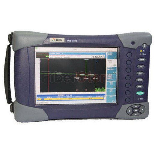
FIBERSTORE Introduced The Smallest OTDR: JDSU MTS-6000


October 28, 2013, FIBERSTORE introduced the smallest optical time-domain reflectometer (OTDR) JDSU MTS-6000, including three types of E8126MR, E8126LR and E8126LRE.
JDSU MTS-6000
JDSU MTS-6000 is a compact and light-weight test platform designed for cellular phone and maintenance of fiber optic network, which weights just 2.4kg. Applying this OTDR tester, field service technicians can provide the best performance level on the market and reliability.

JDSU MTS-6000's modular design enables it to offer a wide range of test functionality, with over 40 different fiber modules supporting an array of applications, and may meet future fiber and photonic testing needs. This new product will go into the market with the name of T-BERD6000 in The united states, during Europe, Asia and all other locations with the name of MTS-6000.

"JDSU MTS-6000 in an extremely compact, lightweight, combined with test instrument in JDSU's MTS-8000 optical test platform multi-network technology leadership," JDSU's gm said: "with our existing fiber optic test application modules to make sure compatibility in our customers in their testing in our solutions maximize roi."

MTS-6000's performance features include an ultra long-range OTDR module. The tester is of comparable products within the first test, in several features within the combined instrument for FTTx, access, metro and core network optical applications. Advanced test head design allows this module to supply the industry's first to become reduced to less than one meter blind tester, allowing higher precision and fault-finding.

Another feature is JDSU's industry-leading UHD module. It's on the market with the highest of any OTDR instrument performance (1550nm wavelengths as much as 50dB). This module's superior performance enables it to operate faster compared to existing 40dB OTDR six times the rate to accomplish the exam, for the network installation and fault isolation saving a lot of time.

Highly integrated design to make sure maximum versatility for triple play, 3G, agile optical networking, FTTx and other new high-speed optical fiber transmission systems are changing the machine structure of the installation and maintenance of way. MTS-6000 OTDRs meet the required cost function for everybody test objectives, and also meet the new test requirements.

MTS-6000 is a highly integrated modular platform having a large high visibility color display (with optional touch-screen display), a high-capacity lithium-ion battery , an optional video fiber scope, and built-in optical test functions for example visual fault locator, power meter, light phone with loss tester. Additional features automatic two-way analysis, insertion loss and optical return loss testing conserve to 50 percent from the ages.

MTS-6000's versatility allows it to satisfy another test applications, for example polarization mode dispersion (PMD), chromatic dispersion, wavelength division multiplexing (WDM) and spectral attenuation measurements. MTS-6000 also because the smallest on the market today dispersion tester sets the standard for such testing instrument.

FIBERSTORE has previously introduced the JDSU MTS-2000 and JDSU MTS-4000, that are a lot more cheaper than the MTS-6000 OTDR and also have good performance along with the new generation. For more product information, check out FIBERSTORE.

2013/10/25

SFPs Find The Position In Commercial Market


Small Form factor Plug (SFP) is a compact transceiver that is popular in telecommunication and for data communication. It uses a device which contains a parent board and interfaces it to a fiber optic networking cable. SFP is mainly made to hold Gigabit Ethernet and various other standard communications in it.
Wide types of SFPs can be found, providing the customer by having an option to choose among various unique models, which suits the apt needs. They will use different set of transmitter types on it facilitating you to find the desired transceiver. The SFP transceiver gives link for getting the necessary optical reach through the existing optical fiber. For instance you will find optical fibers like single mode fiber and multimode fiber separately for appropriate usage. In every mode there are different group of fibers flexible for the users' choice.

In general the rate of signal transmission of SFP module ranges from 100Mbps to 4Gbps. The transceivers work on a distance range varying from 500 meters to 100 kilo meters and also the working wavelength for a number of modules are generally 850nm, 1310nm or sometimes 1550nm. This excellent type of transceiver allows an ease to alter and keep in comparison with other traditional modules. The users can certainly and genuinely replace single module of SFP while the process is running rather than replacing the whole board containing large number of modules in it.

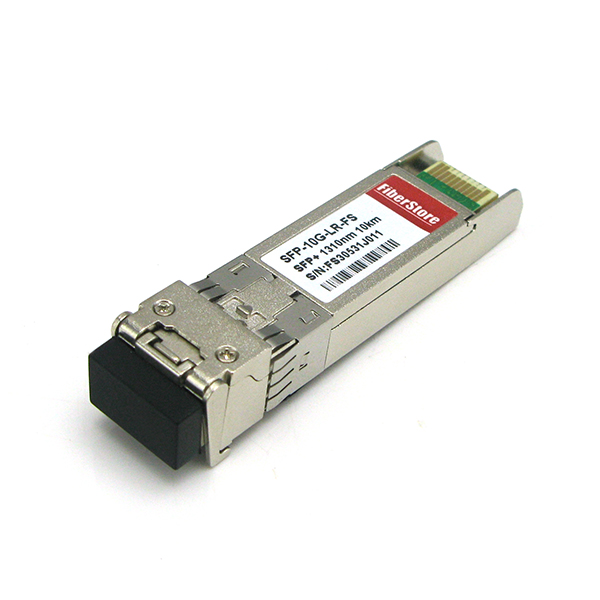
10G SFP
SFP transceivers find the position in commercial market having a capacity to vary data rates as much as 4.25 Gigabits in a single second. The upgraded version namely SFP plus or SFP+ supports data rate as high as 10 Gigabits per second. This rate of transfer is Ten times faster than usual Gigabit Ethernet device. The characteristics of 10G SFP are multifold as following:
  • It can be used instantly connecting to internet.
  • It can be hotly plugged and employed for transferring data.
  • It may withstand temperature up to 70 degree Celsius and may even function at zero degrees Celsius.

Some people might think that SFP would consume more current. Actually, it's not true. SFP consumes less power but is highly efficient in transferring data. In recent times, SFP transceiver can be used for supporting digital diagnostics monitoring (DDM) activities as reported by the standard matching to it. Hence it is employed for digital optical monitoring services. By making use of this element, the user will keep track of the real time limiting factor of the SFP and monitor the optical input power and output power along with temperature and also the voltage way to obtain the transceiver.

There are lots of benefits of using SFP. You could have multiple choices for internet connectivity using this swappable input/output appliance. The device of SFP comes with copper wire interface by which the user can conveniently hold optical fiber communications. It's now possible to transfer SDI video outputs over the coaxial cable through the 10G SFP copper. There is also CWDM/DWDM support in some single mode fiber transceivers.

Nowadays SFP has numerous commercial applications in SONET network, point to point mode of networking, Gigabit Ethernet, metro access networks, FTTD, routers, switches, bridges, servers, etc. It also finds a lot of demand kept in storage area network, local area network, high-speed computer links and switching system. SFP offers large range of detachable interfaces to UTP or coaxial cables and multimode or single-mode fibers.


About the author:
FIBERSTORE is a famous optical communication supplier, who can offer both SFP and SFP+ transceivers with all of varieties, along with other modules for example GBIC, XFP, XENPAK, X2, etc.

2013/10/24

Why Are WDM Technologies So Popular Today


Nowadays the voice, video, and data networks are becoming more complex and requiring more bandwidth and faster transmission rates over ever increasing distances. To fulfill these demands, network managers are relying more about fiber optics. Nevertheless the reality that many providers, enterprise corporations, and government entities are facing is the fact that once their available fiber infrastructure is exhausted, laying more fiber is not really an inexpensive or feasible option. So, so what now?

Many groups are embracing Wave Division Multiplexing (WDM) technologies in order to increase capacity about the existing fiber infrastructure. WDM is a technology which multiplexes multiple optical signals onto a single fiber by utilizing different wavelengths, or colors, related to. By utilizing WDM communication methods network managers can realize a multiplication effect inside their available fiber's capacity.

WDM is protocol and bit-rate independent. WDM-based networks can transmit data in IP, ATM, SONET/SDH, and Ethernet, and look after bit rates between 100 Mbps and 40 Gbps. Therefore, WDM-based networks can hold various kinds of traffic at different speeds over an optical channel. It makes a less expensive approach to quick reaction to customers' bandwidth demands and protocol changes. To control bandwidth and expand capacity of existing fiber optic backbones, WDW-based networks by simultaneously combining and transmitting multiple signals at different wavelengths within the same fiber.

As segmentation and delivering business services tend to be more rampant, WDM optical solutions are becoming a valuable tool for cable operators. Using simple two-wavelength WDM can increase service capacity by twice within the same volume of fibers. For a long time, there've also been some limited solutions using more complicated WDM techniques that may carry four or even more optical signals on the same fiber. Recently cable equipment manufactures have released innovations using WDM that transport multiple broadcast optical signals on the single fiber, making node segmentation more cost-effective and operationally friendly.

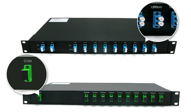
WDM greatly enhances the capacity of systems. You will find mainly two variations of WDM which can be popular: Coarse WDM (CWDM) and Dense WDM (DWDM). Each signal is at a different wavelength and each variation has different capabilities, costs, and operational friendliness, used in different WDM Multiplexer (or Demultiplexer) devices. Multiplexer combines several data signals into one signal for transporting on the single fiber while Demulitplexers separate the signals conversely.
CWDM MUX
CWDM technologies have only been created for HFC networks within the return-path up to recently. Regarding return-path, approximately eight transmitters at different CWDM wavelengths can be multiplexed onto an individual fiber simply by using a CWDM MUX (CWDM Multiplexer). This could be useful when the return-path has a lot more bandwidth contention compared to the forward-path, so 2X4 node segmentation may be sufficient.

DWDM technologies offers much flexibility for node segmentation, yet it's more expensive and operationally challenging than CWDM. The method to segment nodes utilizing DWDM within the forward-path is known as Broadcast/Narrowcast DWDM Overlay. It utilizes two fibers within the downstream: one fiber having an optical signal with all the broadcast content, and something fiber with multiple optical signals on DWDM wavelengths, each containing unique narrowcast happy to obtain a segment. On the node, the narrowcast DWDM wavelengths are separated onto their unique fibers. The narrowcast content will then be overlaid with the broadcast content at the node in a choice of the RF domain or perhaps the optical domain.

As WDM technologies become very popular today, to discover suitable equipment that related to them comes to be so important to networking users. Fortunately, there are various kinds of CWDM/DWDM products available in FIBERSTORE, the biggest supplier of WDM equipments in China who can provide all fiber optic network solutions. Visit the website for additional information.

2013/10/22

Fiber Optic Connector Assembling - Ferrule


Most popular fibre optic connectors being used today possess some common elements. The most critical part, where the fiber is mounted, is the ferrule. Ferrule can be a long, thin cylinder using the fiber mounted in the center hole. The center hole is sized to match fiber's cladding diameter which can be usually 125um.
Fiber Connector Ferrules
The ferrule is mounted inside the connector body and therefore the connector body is attached to the fiber optic cable structure. Finally, a strain-relief rubber boot protects the connector-cable junction. Its job is always to center and align the fiber and protect it from mechanical damage. No more fiber reaches no more the ferrule, where the fiber end is polished smooth either flat or using a curvature. Fiber connector ferrules are made from several kinds of materials including ceramic(Zirconia), stainless steel and plastic.

Unlike most electronic connectors, fiber optic connectors normally do not have the male-female polarity. Most fiber connectors are male only. Instead, fiber connectors mate together in fiber adapters, which are often called mating sleeves or coupling receptacles. Fiber optic adapters used to mate different connector types, such as a FC connector to some SC connector are known as hybrid adapters, plus a bare fiber adapter will be the medium to link the bare fiber to fiber optic equipment.

Although this approach necessitates the use of separate adapters, it otherwise reduces fiber connector inventory requirements since you now need to stock one type of connector only. An additional is that fiber adapters could be made to mate one kind of connector to another, which is a big plus when compared with electronic connectors.

The fiber's plastic coating is stripped first prior to the fiber is inserted in the ferrule. The middle hole with the ferrule is big enough to match the fiber cladding (that is usually 125um after fiber coating stripped off) but tight enough to keep the fiber in a fixed position without any further moving.
Standard bore diameters are 126 1/-0 um for single mode connectors and 127 2/-0 um for multimode connectors. As a result of fiber cladding diameter's variation from manufacturing, some fiber connector manufacturers also supply a selection of ferrule bore sizes for example 124um, 125um, 126um and 127um.

Fiber optic epoxy or adhesive is injected in to the ferrule hole ahead of the fiber is pushed directly into hold the fiber in place. The epoxy or adhesive is then cured rich in temperature oven based on adhesive manufacturers' instruction. Finally the fiber end is polished to some smooth face on polishing films.

The ferrule is then slipped inside another hollow cylinder before it is mounted inside the connector body. The connector body includes more than one pieces that are assembled to carry the cable and fiber in place. Connector person is made of metal or plastic.

The ferrule end protrudes beyond the connector body so that it can slip into the mating sleeves (fiber adapters). A stain-relief rubber boot is finally slipped within the cable end from the connector to protect the cable-connector junction point.

In fiber optic cross connect boxes or fiber patch panels, a range of connector adpators are mounted inside, ready so that you can plug a port fiber cable in a single side as well as an output cable in the other. Fiber connector adapters may also be mounted in wall outlets, just like standard phone jacket.

2013/10/17

Fiber Optic - The Low Cost And Speed Transmission


Electricity is with slow speed and cost. However, anyone can have the latest more sensible choice in data transmission at less the cost and lots of times the speed, the fiber optic.

By using glass or plastic fiber to transmit data, the fiber optic concerns be described as a technology which can switch the position of copper wire. A bundle of glass fibers capable of transmitting messages which can be changed into light waves is what makes the fiber optics. Sharing a variety of technical details within the flowing article, I hope to make you use a better understanding of the subject of fiber optics. The functions will probably be demonstrated by explaining how the technology uses light energy to offer information and data to a selection of sources.

Engineering Science Part of applied science includes data fiber optics and also the engineering behind it is comprised of the science of transmitting data or energy. The basic fundamentals of fiber optics are defined through scientific processes and mathematical equations that fall closely underneath the arena of physics in places you will discover the actual flow with the data may be easily put in observable and replicable systems. So even though a lot of people don't understand what the light is, it could be showed to them through scientific methods.

Fiber optics or optical fibers are often utilized in the concept of imaging optics, sensors, telecommunications, and lighting generally speaking. This can be mainly as a result of data transmission speed cheap it won't require electrical impulses to go the info. It really is resulting in the dependence on electrical power when it comes to data transmission being nearly obsolete since the light transmits energy faster and cleaner than any other know technology.

To grasp the implications on technology by using fiber optics, we must experience how it works when it comes to telecommunications. By conducting signals over distance for communication purposes telecommunications was born. Telecommunications are widespread and there are many devices that assist inside the spread with this communication, like the radio, the fax machine and the television. One of the heavy factors over these mediums is the fiber optics technology.

A telecommunications system's basic fundamentals will be the transmitter, the receiver as well as the transmission medium. A transmitter is definitely an computer that sends an electromagnetic signal using an antenna, essentially taking information and converting it with a signal for transmission which passes it to the transmission medium. A receiver is, of course, the receiving end with the communication channel. The transmission medium may be the material or device that the signal is transmitted.

By serving as an efficient transmitter of data, the fiber optics play an important role in the telecommunications process. Using light energy sent through glass has evolved what sort of world communicates and has revolutionized the process of telecommunications out of this day and into the future. Just click here to get Low Cost Fiber Optic.

2013/10/16

Bare Fiber Adapters Solution - FIBERSTORE

What Is Bare Fiber Adapter?

Bare Fiber Adapter
Bare fiber adapter is the medium to link the bare fiber to fiber optic equipment. Bare fiber adapter has the bare fiber inside on one side, while the other side is a fiber optic connector that can plug into the equipment. It is also sometimes called bare adaptor, or bare connector.
Bare fiber adapters have brought us a very convenient way to connect unterminated fibers with standard FC, SC, ST, and LC. They can be used in some emergency situation for urgent connection. You can simply strip, cleave, clean and insert the fiber into the adapter which has self-locking mechanism, without the hassle of epoxy and epoxy curing steps. When finished, simply push it out with piano wire. They can be used for thousands of times which is very convenient and cost saving. Bare fiber adapters are perfect for power meter hook-ups and temporary system repairs or wherever a quick connection is required.

Bare Fiber Adapter Applications

1) Temporarily connactorizes bare fiber
2) Testing bare fiber, fiber on the reel, fiber before and after installation
3) Production line of fiber optic devices
4) For fast and temporary fiber optic connections in communication system
5) Temporary connections to OTDR tester, Power Meter, Talk sets, Demo Equipment and Dark Fiber

How To Use Bare Fiber Adapter

1) Strip the outer jacket to about 3 inches
2) Strip the buffer coating leaving about 2 inches of fiber exposed
3) Score and Cleave the fiber, leaving 0.5 inches bare fiber exposed.
4) Once it is cleaved, clean the fiber with Isopropyl alcohol and Kim wipes.
5) Press the clamp button on the bare fiber adapter. Insert the cleaved fiber in the rear of the housing until the glass is flush with the end of the ferrule. Release the clamp button, securing it in place.
Tips: You should not use the adapter with a light source, because physical contact is required at the launching end of a test station. But you can use the adapter with a power meter, just make sure the power meter has a wide-area detector.

FIBERSTORE Bare Fiber Adapters

FIBERSTORE can supply LC, SC, FC and ST bare fiber adapters with stable qualities that use high quality ceramic ferrules and precise fiber connector housing parts. The adapter ferrules are usually Zirconia (a type of ceramic). Zirconia provides high stability and repeated use without worn out.
LC FC ST SC bare fiber adapter
FIBERSTORE bare fiber adapter's body is designed to accept connector modules. It is totally reusable. If a fiber happens to break off inside the adaptor, simply loosen the thumb screw and remove the connector module from the adapter body. The removable connector module feature allows the user to clean out the broken debris directly from the ferrule. The connector modules are not only removable, but also interchangeable. When an application requires a different type of connector, remove the current connector module from the adapter body and replace it with the desired type.

FIBERSTORE Bare Fiber Adapter Features

1) Fits accordingly LC, FC, ST ,SC adapters
2) Lightest weight and very compact size
3) Specially designed mechanism minimizes insertion loss
4) Easy to operate
5) User friendly - easy to insert, remove and reload fiber
Article source: Bare Fiber Adapters Solution

2013/10/15

Fiber Optic Cable Termination Steps


In fiber networking installations, workmanship is critical to reach acceptable results because even a small imperfection or microscopic dirt on the face of the fiber can result in significant problems with optical propagation. To help installer avoid these problems, this article offers a hands-on tutorial for fast, safely, and correctly creating fiber optic connections that meet good standards of quality workmanship and ensure optimal coupling efficiency. The following steps for fiber optic cable termination will provide a solid base of information that will have great reference value for both new and experienced field technicians those terminate fiber optic cables often.

1. Insuring Safety
First of all, you should protect yourself during the installation process and leave the installation area in a safe condition for other people beside you. Fundamental safety tools include a dark work surface, such as a black work-mat, and a proper trash receptacle for fiber scraps that is clearly marked as to its contents. Using a piece of black tape to stick your scraps on isn't an acceptable work practice other than just incorrectly flick off the cleaved fiber scraps with fingers which could be harmful to the occupants nearby. Then, use a fiber optic microscope to check a fiber to make sure the other end isn't connected to a power source since the invisible laser light is harmful to the eyes while you may not eve realize you're looking into it until it's too late.

2. Stripping
Once you have got your bulk fiber cable, strip the cable down to the bare fiber using an appropriate fiber stripper. After you have prepared the end of the cable you may begin to mix the epoxy resin and hardener together and load it into a syringe, unless of course you are using pre-loaded epoxy syringes, which are premixed and kept frozen until use. Now, from the syringe you must inject the epoxy directly into the connector ferrule.

3. Inserting
Injet epoxy into the fiber optic connector ferrule and then insert the fiber optic cable so that the cable is seated inside of the connector wall and the bare fiber core sticks out about a half an inch from the front of the ferrule.

4. Crimping
If your cable is jacketed, you will need to use a crimping tool to secure the connector to the jacket and strength member of the cable. Two crimps would be needed at this point.

5. Curing
After that, the next step is to place the connected end into a curing holder to ensure that the end of the fiber is not damaged while curing. Now place the cable and curing holder into a curing oven. To avoid flicking while curing with a conventional oven, situate the connector so that the end is facing down. This positioning will ensure that the epoxy does not come out of the back side of the connector and compromise the strength member of the cable. Then you need to refer to the documentation of your specific epoxy for accurate curing times and temperatures.

6. Cleaving
After you have sufficiently cured the epoxy, you are now ready to move on to the next step, cleaving the excess protruding fiber core. The tool you need is a fiber optic cleaver. Get as close to the ferrule tip as possible while avoiding any sort of twisting motion.

7. Cleaning
Once cleaved, it is important that you properly dispose of the fiber clipping. A regular piece of tape will do just fine at retaining your fiber debris. If you do not properly dispose of all fiber pieces they could easily end up in your skin or even in somebody's eye or respiratory system. A short strand of fiber can cause more damage than you would at first imagine.

8. Polishing
After the excess fiber cleaved and properly disposed of, you can begin the task of polishing the fiber tip to a smooth finish. Using fiber optic polishing tool you can effectively remove any excess epoxy from the ferrule end and buff out any imperfections on the face of the fiber. You can polish the cable tip with the 5-15 micron film, 5 micron aluminum oxide film, 3-6 micron diamond film, 1 micron diamond film, and HX film in order. A smooth fiber surface makes great sense to any light passing through.

9. Cleaning Again
If you have finished with your polished finish, you can move on to the cleaning of the ferrule and fiber tip. Using a lint-free wipe dipped in 99% reagent-grade alcohol, gently wipe the surface area of the ferrule and fiber tip and immediately wipe them dry with another dry lint-free wipe. You may optionally use a can of compressed air to finish the process.

10. Testing
Now the connected cable is complete. The last step is to ensure good standard. First you need to inspect the fiber tip with a 100x to 200x fiber optic microscope. And then test your cable with a fiber optic test equipment for insertion loss and return loss where needed.
In addition, most tools which are used in the steps can be found in a Fiber Termination Kit. Fiber termination technicians should keep such a kit by the side for much more convenience.


About the author:
FIBERSTORE is a famous Chinese fiber optic products supplier. It supplies almost all the fiber network solutions including bulk fiber cable, tranceiver modules (SFP, GBIC, XFP, etc.), fiber optic patch cables and cable managements (such as fibre termination box). Visit the website for more details.

2013/10/10

The Advantages Of Fiber Optics Compared to Copper Cables


Should you be looking for a new ISP, question them about fiber optics on the network. Here are a few avantages that differentiate fiber optics from copper cables.
  • Electricity VS. Light
The greatest problem with copper cables is the fact that them all require electricity and in many cases significant amounts of it. You need to think about the outcomes of operating an information network which is heavily reliant on electricity to deliver signals. This is currently when our electrical grids are falling apart and today the cost of energy is merely increasing. However, fiber optics do not rely on electricity to transmit data as it uses light the industry lot cheaper.
  • Signal Degradation
One of the leading problems would be that the strength of the electrical signal degrades while on a trip through copper cabling. Same is true for light as it travels through fiber optic cabling, but only a fraction of the loss when compared with copper cables. The more a sign degrades, the greater hardware and sub-stations have to be placed in order to interpret these signals and also to make certain that there's correct transmission from point 1 to suggest 2. More hardware support is required in this case.
Another side effect of degradation in electrical signals is heat and what it does in copper cables along with computers. So, this leaves these networks available to potential failure.
  • Upgrades
To be able to support complex signals, more wiring and hardware upgrades are required in the event of traditional copper wiring. Since fiber cabling is not actually affected as a result of heat when compared with copper cables, upgrades are fewer in addition to simpler to perform. Providers with existing wire networks are constantly taking care of ways to boost the performance of existing networks, nevertheless the limits related to sending electricity over copper wiring are really even more than with fiber optic cables that it is wiser to get fiber setups.
Compression algorithms are used to help traditional copper networks, however, this eventually ends up using the users needing to spend more money on more costly modems that are needed to take care of encoding/decoding in addition to compression techniques that are made more complex to keep the copper cables from degrading.
  • Effects on Consumers
What does this suggest to consumer - digital television, digital phone services and broadband data plans all using the same fiber optical wire without causing any bottlenecks, congestion, and little data loss. Which means fiber optic networks tend to be more economical in performance, features, and cost. So, this is the way forward for the whole data systems in businesses and houses - fiber optic cable - reliable, low cost plus more features. You may contact FiberStore to get more information on fiber optics prior to going for this as a means of communication for your individual or business needs.


About FiberStore:
FiberStore is a largest supplier of fiber network solutions in China. It is possible to buy optical cable with good quality and reasonable price from the website. You can find all selections including figure 8 fiber optic cable and plastic optical fiber.

The Main Services of Internet


Internet was created a long time before we now have noticed it. Today we're not able to imagine life without it. Our way of life rely on the web services even if we do not have a PC. It it hard to visualize life without internet since it was difficult to imagine life without electricity three decades ago.
Internet is really a worldwide network, only a network. The help are what allow us to to transmit a message or to make a move. There are lots of those who believe that internet is WWW(World Wide Web) and the other way round. Actually, WWW is only one with the services that are available over the internet. The key internet services include ISP(Internet provider), Email, WWW and Spam.
  • ISP
So that you can hook up to the web you'll need a contract by incorporating ISP. Access to the internet can be made available over analog phone line, ISDN(Integrated Services Digital Network), various xDSL(x Digital Subscriber Line) technologies, FTTH(fiber to the home), wireless networks, cable network, etc.. The speeds vary but it's not uncommon to get 100 Mbit/s as well as 1 Gbit/s via FTTH. Regardless of the connection speed, internet access is crucial.
  • Email
Sending electronic messages is among the extremely popular internet services. So that you can send and be given a message you will need a minimum of two mail servers, one for sending and one for finding the message. Since email address is really a prerequisite for almost any business, not only online, each company has at least one mail server. Fortunately there are lots of free email providers. One of the most popular and famous is Gmail, free email from Google. Without a Gmail account you're missing a lot.
  • WWW
WWW is probably the most widely used websites. This might be the reason why www means exactly like internet to numerous people. Using a homepage is a must. Not merely for companies but in addition for communities, clubs, organizations as well as individuals. Writing your blog is very popular these days. Due to this popularity there exists a huge competition among internet hosting providers. The costs are low, establishing a website is pretty simple and merely anyone can have his or her own website.
  • Spam
Spam is not an online service but it's a direct results of cheap or even free internet services. It's so simple to create a contact and send it to any address. And sending what it's all about to an incredible number of worldwide contact information is not any different. Email spam is a huge problem. There are many businesses that are selling anti-spam products or services. One excellent anti-spam filter is used by Gmail. You'll rarely get a spam email. A big spam on the internet. There are lots of pages offering no useful content. When you're trying to find something it is likely you will find such page.

Of course, there are also other services on the internet. Sending IP packets is easy each modern appliance or consumer electronics posseses an ethernet connector. Don't be surprised a huge increase of communication over internet.


About the author:
Morph Sun is experienced of fiber network solution in FiberStore, a largest Chinese fiber optic cable supplier. As fiber optics play a most important role in the current Internet Networks, we try our best to provide good quality fiber optic products to meet the market's needs.

2013/10/08

Trends In Fiber Optic Communication Industry


Fiber optic communication industry has been enjoying amazing growth for nearly 20 years, which is driven by both technology advance and market demand. There are some obvious trends inside the growth and development of new technology and market. All-Optical Network and Multi-Terabit Networks could possibly be the first two.


All-Optical Network

All-optical network has become a top topic in fiber optic communication niche for over a decade. Its ultimate goal would be to process all signals in the optical domain with no conversion and controlling to electrical domain in any way.
However, most signal routing, processing and switching occur in the electrical domain up to now. Optical signals must be converted to electrical signal first, and then the electrical signals are processed, routed and switched to their final destination. Following your processing, routing and switching, the electrical signals will be converted to optical signals which can be then transmitted over long distances. This technique is called the O-E-O process.

But this O-E-O process severely limits the rate with the network. Why? Since optical signals can process data faster then today's electronics. The O-E-O process is a bottleneck preventing us from achieving even higher data rates. This bottleneck results in a tremendous interest in all-optical networks where no electronics are required for signal processing, routing and switching.
The advantage of all-optical network is that since all signal processing, routing and switching occurs in optical domain, there is no need to switch the electronics when data rates increase. For instance, current fiber optic transmitters and receivers are equipped for just one single data rate, thus, they ought to be replaced if the data rate increases. But this won't be necessary in a all-optical network.

Admittedly, all-optical network involves be trend of fiber optic communication. However, many obstacles still lie in our approach to make all-optical network a real possibility. Some functions for example reading headers about the optical signals, switching the optical signal on the fly in line with the header content and real-time wavelength switching are just a few of the serious challenges that should be solved before we are able to have a true all-optical network.


Multi-Terabit Networks

DWDM opens the door to multi-terabit transmission. The interest in developing multi-terabit networks is driven through the increasing accessibility to more bandwidth in fiber optic networks.
DWDM SYSTEM
One terabit network was achieved by using 10Gb/s data rate combined with 100 DWDM channels, while four terabit network may be accomplished by combing 40Gb/s data rate with 100 DWDM channels too. Researchers move their target to even higher bandwidth with 100Gb/s systems. This kind of speed is extremely expensive for make and may just be justified on long-haul systems. However with the price reduction on fiber optic components, devices and systems, more bandwidth is not definately not us.

There are a few other major trends in the fiber optic communication industry too. The most important ones include expansion into mass markets (FTTx), miniaturization, new technology development, cost reductions and even more.


About the author:
Morph Sun is a fiber optic network expert in FiberStore(FS). FS is a best fiber optic products supplier who can offer most FTTx solutions including CWDM/DWDM modules, transceivers, fiber optic cables, patch cables and so on. For more information such as fiber cable price, figure 8 fiber optic cable and plastic optical fiber, please visit our website.

2013/10/07

Modern Network Cabling Needs Fiber Optic Cables


Network Cabling is important for smooth running of business in big organizations where you can find innumerable computers nowadays. Structured cabling is the first step toward all business networks because it provides impeccable connectivity between computers, servers, and lots of other network devices, which permit both data and voice being transmitted all over the world easily.
Most cabling professionals use three basic kinds of cables because both versions is discussed below:
  • Co-axial cables: probably the most commonly used cables for establishing a wide range of networks. The co-axial cables include a copper core which is enclosed in foil insulation and is then covered with a layer of braided metal shielding. In areas which have problems with advanced level of interference, Network cabling installation professionals generally use co-axial cables having additional layers of both foil insulation and braided metal shielding.
  • Twisted-pair cables: generally split into two sub-categories, namely shielded twisted-pair cables and unshielded twisted pair cables. The cables have core of your pair of insulated copper wires which are wound around one another. As a result of the twisting of the couple of cables, the interference caused by noise or other signals emitted from various gadgets put into their vicinity is minimized.
  • Fiber optic cables: undoubtedly given greater preference by network cabling installation professionals, especially in cases when the protection, quality and high speed bandwith are of utmost importance. These cables use high-speed modulated light pulses to transfer data and contain both sending and receiving strands. The main of each of these strands is made from extremely thin glass, which is enclosed within con-centric layers of glass referred to as cladding. Each cable contains one sending strand and receiving strand that are then covered by a protective jacket to make it able to sending in addition to receiving data without having affected its quality.
As technology is advancing daily, the demand for more contemporary and fast types of network cabling is surging, now the fiber cable provides the good result and lots of companies have started utilizing it for installing data cabling infrastructure. It is because there are plenty of advantages of fiber cable, including the ones the following:
  • 1. Fiber optic cable can carry signals approximately 50 times longer as compared to the copper wires, because it has very low signal loss rate, and doesn't require a signal repeater to maintain the integrity with the signal over long distances, unlike the copper wires.
  • 2. In a cabling system that involves copper wires, you'll be able to detect a sign which is being transmitted through the cable remotely, which eventually presents the loopholes in their security. However, it is not possible regarding fiber optic cable because its dielectric nature can make it impossible to detect the signals remotely.
  • 3. Fiber cable has long length, small diameter, and is very light-weight, which eventually makes the installation and upgrade process pretty easy and inexpensive if compared with copper wires.
  • 4. This sort of cable provides higher bandwidth and knowledge transfer rate, which eventually cuts down on download some time and increases the network efficiency.
  • 5. This cable can be installed in high Electromagnetic Interference (EMI) areas, because it does not have metallic wiring, which eventually makes it completely resistant against EMI.
  • 6. This networking cable is very durable and long-lasting, and can be relocated many times.
Since it might be the most important cable in Network Cabling, it's important to discover suitable and cost-effective fiber optic cables to fulfill the business needs. FiberStore supplies all kinds of cables including not just copper cables but also bulk fiber cables for example multimode, single mode, simplex, duplex, outdoor/indoor, ADSS, armored, figure 8 fiber optic cable, and POF cable etc..

2013/10/04

Optical Fiber Connector Q & A


Q: What is optical fiber connector?
A: Optical fiber connector is used to join optical fibers where a connect/disconnect capability is required. The basic connector unit is a connector assembly. A connector assembly consists of an adapter and two connector plugs. Due to the polishing and tuning procedures that may be incorporated into optical connector manufacturing, connectors are generally assembled onto optical fiber in a supplier's manufacturing facility. However, the assembly and polishing operations involved can be performed in the field, for example, to make cross-connect jumpers to size.

Q: Where are optical fiber connectors used?
A: Optical fiber connector is used in telephone company central offices, at installations on customer premises, and in outside plant applications to connect equipment and cables, or to cross-connect cables within a system.

Q: What is the structure of optical fiber connector?
A: Most optical fiber connectors are spring-loaded. The end faces of the fibers in the two connectors are pressed together, resulting in a direct glass to glass or plastic to plastic contact. This avoids a trapped layer of air between two fibers, which would increase connector insertion loss and reflection loss.

Q: Which parameters do optical fiber connectors have?
A: Every fiber connection has two values: Attenuation or insertion loss; Reflection or return loss. Measurements of these parameters are now defined in IEC standard 61753-1. The standard gives five grades for insertion loss from A (best) to D (worst), and M for multimode. The other parameter is return loss, with grades from 1 (best) to 5 (worst).

Q: What types do optical fiber connectors have?
A: There are many types of optical fiber connectors, including FC, LC, SC, ST, D4, MU, MPO, SMA, MTRJ and E2000 etc.. SC and LC connectors are the most common types on the market. The main differences among them are dimensions and methods of mechanical coupling. Generally, organizations will standardize on one kind of connector, depending on what equipment they commonly use. Different connectors are required for multimode, and for single-mode fibers.
In datacom and telecom applications nowadays small connectors (such as LC connector) and multi-fiber connectors (such as MTP connector) are replacing the traditional connectors (such as SC connector), mainly to provide a higher number of fibers per unit of rack space. (MTP stands for: Multifiber Termination Push-on connector. It is built around the MT ferrule. Each MTP contains 12 fibers or 6 duplex channels in a connector smaller than most duplex connections in use today. It is designed as a high-performance version of the MPO and will interconnect with MPO connectors. MTP connector is manufactured specifically for a multifiber ribbon cable. The single mode version has a angled ferrule allowing for minimal back reflection, whereas the multimode connector ferrule is commonly flat. MTP connector allows high-density connections between network equipment in telecommunication rooms. It uses a simple push-pull latching mechanism for easy and intuitive insertion and removal. The end of MTP connector may be polished flat or at an 8° angle. It is the same size of a SC connector but since it can accommodate a maximum of 12 fibers, it provides up to 12 times the density, thereby offering savings in circuit card and rack space. Click to view MPO fiber price.)

Q: What features does a good optical fiber connector have?
A: Low Insertion Loss; Low Return Loss; Ease of installation; Low cost; Reliability; Low environmental sensitivity; Ease of use.

Q: Where can I buy high cost-effective optical fiber connectors online?
A: FiberStore is the best choice strongly recommended to you.